
"While it is easy to imagine structures without architecture, there can be no architecture without structures"
Thus, as architectural designers, we should understand the following fundamentals of structural design.
In this post, we will cover the following:
Overview of Structural Design
Terminology
1 - Basics
2 - Systems
3 - Case Studies
What is Structural Design?
All building structures share the same function: To transmit the loads applied on a building safely to the ground conserving its stability and stiffness.
There are several ways to achieve that goal with the use of the different assembly of construction structural elements and materials.
To get there is important to know how loads, moments, deformations and other variables can act on a building and the different structural systems that exist to apply the solution that will best suit a particular scenario.
Why is Structural Design important?
Architecture is built primarly to be inhabited, so structures should provide the stability required to don’t fall down and face any circunstance safely.
Althought the structural analysis of a building is done primarly by structural engineers, it is important for architects to have in mind since the start of the design process how the structure can be resolved.
This will result in more grounded design decitions, less conflicts between disciplines and a better understanding of the project as a whole.
Terminology
Bending
The effect of transverse loads being applied to an element.
Bending Moment
Internal reaction due to a perpendicular force applied on the axis from a given distance (moment) which causes the structure to bend.
Compression
Force created when two loads are pushing against
each other.
Deformation
Change in shape or size of an structural element.
Equilibrium
State in which all the forces and moments acting on an element are balanced by opposite forces keeping the body at rest.
Failure of Structure
Anything that prevents the timely or safe occupancy of a structure, whether is an actual collapse or significant instability.
Force
Physical influence, caused by a load that when unballanced will change the state of rest in a body.
Load
Forces, deformations, or accelerations applied to a structure components.
Moment
A rotational force that occurs when a force is applied perpendicularly to a point at a given distance away from that point.
Shear Force
The effect of two loads of opposite direction acting in two different planes within the structural element
Stiffness
Ability of a structure to resist excessive deformations.
Stress
Measure of an external force acting over the cross sectional area of an object.
Structure
A number of material elements working together, providing strength, stiffness, and stability in order for loads to be held aloft.
Tension
The effect of two loads pulling away from each other in opposite directions.
Adapted from “The Structural Basics of Architecture” by Bjorn N. Sandaker, Arne P. Eggen & Mark R. Cruvellier -2nd Edition
1 - Basics
Structures play a huge role in architecture, as they are the elements that allow buildings to withstand the action of loads such as gravity, wind, earthquakes, impacts and other environmental sources.
The most important issue is to prevent the collapse or other catastrophic failure of the structure when exposed to extreme loadings. That's why is important to determine the most extreme loadings that the structure can encounter in its design life as well as the forces generated internally within the structure due to those external loadings.
The structural analysis is the process where structural engineers calculate the loads, moments, stresses and other variables that can cause acceleration, rotation or deformations in the structural elements and the proper reaction forces to counteract these actions and maintain stability.
See below slideshow for more details.

Forces
Unit of measurement: Newton (N)
A force is a physical influence, caused by a load that when unopposed, will move a body in the direction of its action.
Forces are vectors defined by their magnitude and their direction. They can also be split into components in such a way that their sum is equivalent to the original force.
Splitting them into horizontal and vertical components results very practicaI being the case that most beams and floors are horizontal and most columns and walls are vertical.

Moments
Moment : Force x Distance
In addition to the tendency to move a body in the direction of its application, a force can also tend to rotate a body about an axis.
This rotational tendency is known as the moment (M) of the force or torque.
Moments can be either negative or positive depending on the sense of the rotation.

Bending Moments
Bending moment : Force x Distance from fixed point of support.
A bending moment is a moment whose rotational force is resisted.
When a force is applied on a body far away from a point of support, the structural element will tend to bend.
This concept is used in architecture to calculate where, and how much bending may occur on an structural element.
The most common structural element that is subject to bending moments is the beam.

Statics
First Newton’s Law:
An object at rest will remain at rest when acted by ballanced forces.
When acted by unballanced forces an object at rest will move with the direction an magnitude of the resultant force.
Third Newton’s Law:
For every action, there is an equal and opposite reaction.
Since we cannot allow structural parts to move, we must be certain that the resultant forces acting in the structure are met by equally large but directly opposite forces, thus maintaining equilibrium.

Loads (Dead and Live Loads)
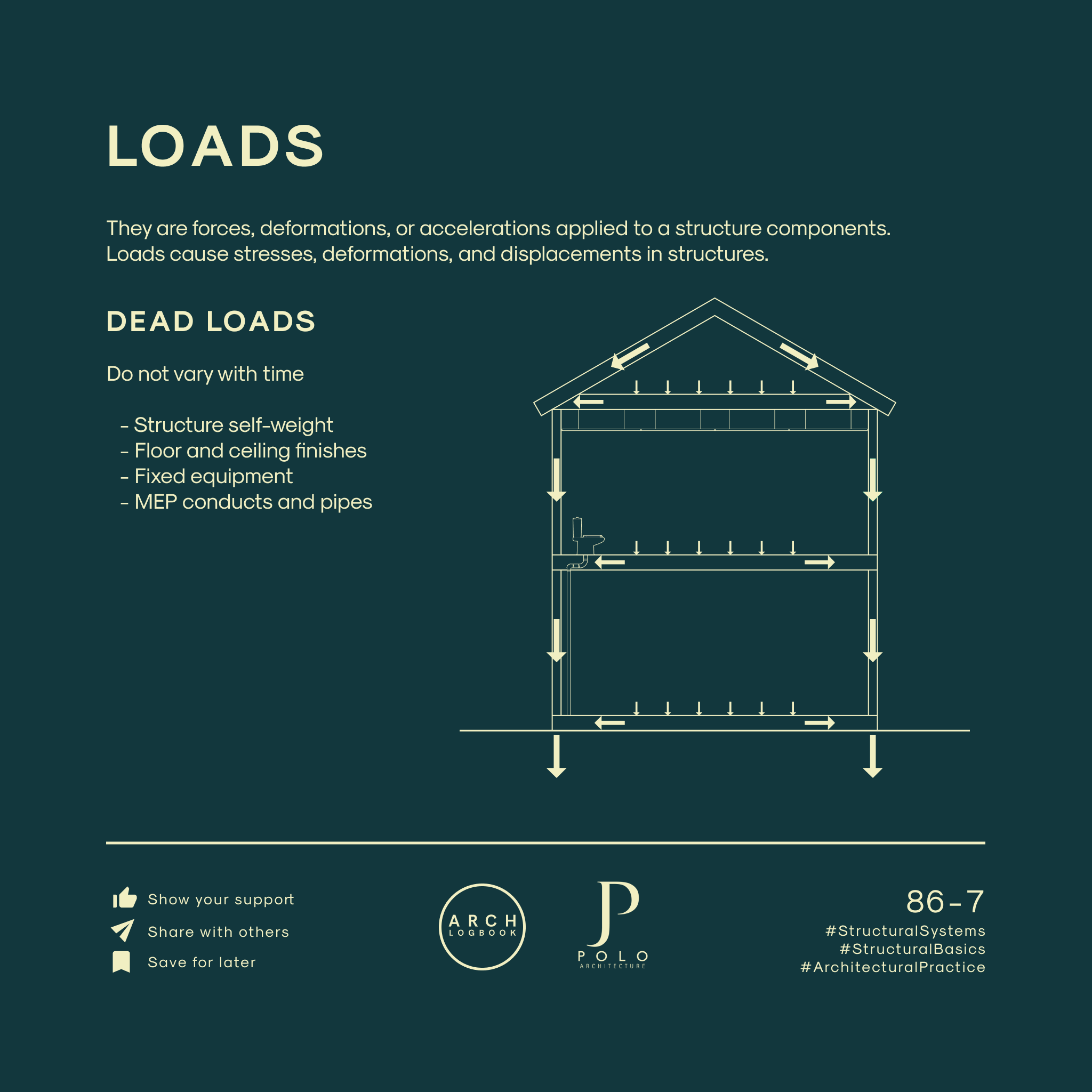
Loads are forces, deformations, or accelerations applied to a structure components.
They cause stresses, deformations, and displacements in structures.
Dead Loads do not vary with time
Examples
- Structure self-weight
- Floor and ceiling finishes
- Fixed equipment
- MEP conducts and pipes
Live Loads vary with time
- Occupancy loads (given by building codes)
- Furniture and other innanimate objects
- Enviromental loads (Wind, earthquakes, snow, water pressure)

Stresses & Deformations
External forces (loads) produce interal forces (stresses) that result in deformation (changes in shape or size) that can lead to the failure of the structure.

2 - Systems
An structural system is the assembly of components connected in such a way that they can withstand the action of loads applied to it.
In architecture, there're several ways of classifying these systems depending of their function, materiality, spans, and the way they primarly support loads.
It is important to consult the respecting building codes for guidance in allowed materials, minimum dimensions and other recommendations.
Here are presented the most common systems used in the architectural practice, however most buildings and structures are usually composed by a combination of these systems working together.
The understanding of how structural elements behave and interconnect with each other to transmit loads safely to the ground can give more clarity to the architectural practice and facilitate the communication of our ideas to engineers and other specialists.
Systems include
- Bearing Walls
- Frame Structures
- Thin-Shells
- Truss Structures
Bearing Walls
Bearing walls consists of walls that bear the weight of floors, roofs and other elements above them in addition to their own weight.
These walls conduct the loads to a foundation structure.
Common wall materials:
Thick heavy walls of
- Brick
- Stone masonry
- Reinforced concrete.
Common floor/roof slab materials:
- Reinforced concrete
- Wood
- Steel members

Frame Structures
Frame structures are the most common form of modern structure.
It consists in a network of columns and connecting beams that forms the structural ‘skeleton’ of a building.
This grid is typically constructed on a concrete foundation and is used to support the building’s floors, roof, walls, cladding and so on.
Common columns / beams materials:
- Reinforced concrete
- Steel profiles
- Wood
Beams:
- The horizontal load-bearing members of the frame.
- Work mostly under tension
Main beams:
Transmitting floor and secondary beam loads to the columns.
Secondary beams:
Transmitting floor loads to the main beams.
Columns:
- The vertical members of the frame and the primary load-bearing element.
- Work mostly under compressive forces
- They transmit the beam loads down to the foundations.

Thin-Shell Structures
Thin, usually curved plate structures shaped to transmit applied forces by compressive, tensile, and shear stresses that act in the plane of the surface.
This forces are known as membrane stresses.
Common materials:
- Concrete with a steel mesh reinforcement
- Tensioned fabrics

Types of Thin Shell Structures include:
1) Concrete shell structures:
Often cast as a monolithic dome or stressed ribbon bridge or saddle roof.
2) Lattice shell structures:
Gridshell structures often in the form of a geodesic dome or a hyperboloid structure.
3) Membrane structures:
- Fabric structures and other tensile structures
- Cable domes
- Pneumatic structures.

Truss Structures
It’s a structure that consists of connected triangles organised in a way that the whole assembly behaves as a single object.
The members of the truss transfer load through compression and tension, so all members join together to be free of bending and shear.
Advantages of Truss Structures:
- Long spans
- Light weight structures
- Reduced deflection.
- Support heavy loads.
Common materials:
- Metallic (aluminium, steel)
- Wood

Types of Truss Structure include:
- King Post Truss
- Queen Post Truss
- Town lattice truss
- Long truss
- Howe truss
- Pratt truss
- Warren truss
- Scissors truss

3 - Case Studies of Structural Design
In this section, we will go through case studies for 4 types of structures:
- Bearing walls, frame structures, thin shell structures and truss structure.
Bearing Walls - Monadnock Building, Chicago (USA) by Burham & Root
This 16-story and 215 feet tall skyscraper is considered the tallest and the last load bearing masonry wall skyscraper ever constructed. Resting on a floating iron reinforced concrete foundation, its structure consists primarly of an envelope of thick structural masonry walls braced in part by steel portal framing only for the windows and the internal frame to resist wind forces. As a result the walls had to be eight feet thick in the basement and six feet thick on the ground floor in order to resist the weight of the structure.

Frame Structure - Seagram Building. New York, USA.
(Mies van der Rohe)
One of the most famous examples of corporate modernism in architecture, the Seagram building is built around a steel frame with large glass walls on the outside, being the latter non-structural and hung from the frame itself. Rohe took the functionality of the structure as its source of beauty and aesthetic value. That's why although building codes didn't allowed the steel structure to be visible, Rohe placed bronze I-beams on the outside to give the illusion of structural steel.

Thin Shell Structures - Los Manantiales restaurant. Xochimilco, Mexico. (Felix Candela)
Known by his mastery in thin-shell concrete construction, Candela created an elegant work of structural art with Los Manantiales restaurant. The structure consists in the circular array of four intersecting hypars (hyperbolic paraboloids) that form a thin roof surface over a dining space. The largest membrane forces are carried along the intersections between the forms, called the groins. This areas are thickened by creating hidden steel reinforced “V” beams. The rest of the structure has minimal reinforcing to address creep and temperature effects, but essentially works entirely in compression.

Truss Structure - Milstein Hall. New York, USA. (OMA)
This project consists of 25,000 sqf flexible studio space at Cornell’s College of Architecture, Art and Planning. The structure is built with an unique hybrid truss system of 1,200 tons of steel supporting two big cantilevers and connecting with two important existing halls on campus.
The exposed hybrid trusses were designed to balance structural efficiency at the cantilevers and maintain open circulation within the large open plan.

Pro Tips
Consider the Safety Factor
That’s the structure capacity to bear extreme loadings which could have a very low probability of occurrence. It will be the main concern in any structure.
Understand the Loads
The calculation of the live loads of a structure will depend of:
- Occupancy loads (this number would be given by the respective building codes according to the use).
- Furniture and other movable equipment weight.
- The enviromental conditions of the site, which will dictate the wind, snow ot other loads that can apply.
It is important as well to look at the seismic hazard maps of the region to determinate the possible earthquake forces.
In addition the dead loads will be the result of the structure self-weight as well as the weight of fixed equipments as bathroom appliances, MEP pipes, roof, ceilings and floor finishes, etc.
Determine Structural Grid
As a rule of thumb, for spans of more than 30m without columns it will be neccesary to apply a truss system or even some type of thin-shell structure. Meanwhile for a high-rise building either a reinforced concrete or a steel frame structure would be the most viable option.
Know your building codes
Building codes have structural regulations in order to ensure earthquake-resistant buildings.
They will dictate minimum dimensions for columns, beams; allowed materials; minimum steel reinforcement for concrete structures, etc.
Further Reading
The Structural Basics of Architecture by Bjorn N. Sandaker, Arne P. Eggen & Mark R. Cruvellier
Fundamentals of Structural Engineering by Jerome J. Connor & Susan Faraji


